|
In Chapters 3 and 4, we used position, velocity, and acceleration to describe motion in one dimension. In this section we broaden our scope to include the full, three-dimensional vector character of these quantities. Position, velocity, and acceleration are vectors; the tools we learned with one-dimensional motion can now be extended to three dimensions. The key to working in three dimensions is to use vector components to separate complex, three-dimensional problems into three separate but solvable one-dimensional problems—one along each coordinate axis. 
|
Displacement vector
|
Suppose you walk 10 m east, turn, go 5 m north, then turn and go 5 m west. Where do you end up? To answer the question, you must treat each leg of the walk as a separate displacement vector. The displacement vector describes a change in position, such as a move from one place to another. The position at the end of the walk is the result of adding the three displacements together. This resultant vector is also the final position vector. The illustration below shows the calculation done graphically and by components, resulting in = (+5,+5) m. Note that the westward displacement vector has a negative x-component because the positive x-axis points east. Displacements are often given in compass coordinates in which the x-axis is east–west and the y-axis is north–south. 
|

|
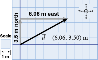
 Most real displacements are not purely north, south, east, or west. Instead, they are at angles that can change over time. For purposes of calculation, however, it is useful to represent a displacement by components as if it were two separate displacements in x and y. For example, moving 7 m at 30° north of east puts you in the same place as moving 3.5 m north and then 6.06 m east. The displacement is written in component form as = (+6.06,+3.50) m, even though the actual motion follows the diagonal path.
 |
 If your factory has manufactured a part, how do you know whether it came out the right size? If the part is a simple shape, such as a cube, then it might be straightforward to measure its dimensions with a hand tool, such as vernier calipers. But how can you check the dimensions of the part if it has a complicated shape?
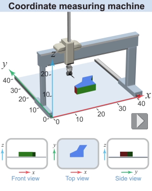
A coordinate measuring machine (CMM) is a member of a class of technologies that measure the shape of an actual part so that it can be compared with the designed shape from the original CAD (computer-aided design) program. Some coordinate measuring machines are mechanical: they use a physical probe that traces the surface of the part and measure the locations of the surfaces in (x, y, z) coordinates. Another kind of CMM uses a laser that moves around the part and measures the locations of the surfaces using laser metrology. In either case, the probe moves around horizontally on an x–y stage, which measures two of the coordinates. The probe can also move vertically to measure the z-coordinate. Using the measurements, the operator constructs a three-dimensional computer model of the actual part, which can then be compared to the three-dimensional computer model of the original design. If the measured part is within the prescribed tolerances of the design, it can be accepted and shipped to the customer. The CMM is an instrument that can play an important role in the quality control in a manufacturing process, leading to fewer customer complaints or returns of faulty products. 
|
The illustrations above depict displacement using a vector model, where each displacement is represented by a vector. In the vector model, more than one vector can be added graphically using the head-to-tail method or algebraically by adding the components. 
|
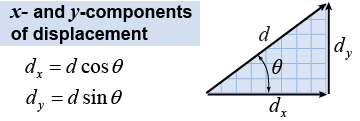
 Calculating the components of a displacement vector is the same as for the force vector. If the magnitude of the displacement is d, then the components are dx = d cos θ and dy = d sin θ.
|
Two displacement vectors are = (+3,+9) m and = (−6,+2) m. - What is + ?
- What is − ?
 |
-
- In order to subtract the vector, you instead add the negative of vector . Since − = (+6, −2) m, the difference is

|
| |
|

