|
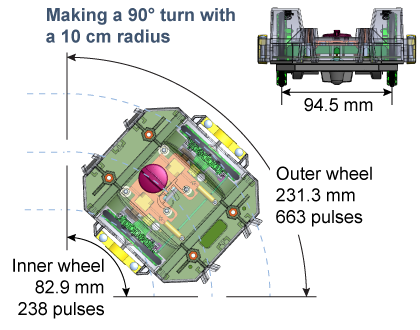
 To make accurate turns we put separate encoders on the left and right wheels. To make a turn, one wheel moves farther than the other. The ErgoBot has a width of 94.5 mm between its wheels. In order to make a 90° turn with a radius of 100 mm, the inner wheel travels 82.9 mm while the outer wheel travels 231.3 mm. This corresponds to 238 pulses from the inner wheel and 663 pulses from the outer wheel.
|
To make a zero radius turn, one wheel moves forward while the other wheel moves backward an equal amount. For example, to make a 90° turn the right wheel moves forward 74.2 mm (213 pulses) while the left wheel moves backward −74.2 mm (−213 pulses). The angle of the turn is determined by the width between the wheels and the resolution of each wheel. 
|
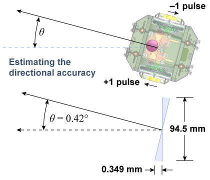
 The maximum angular error occurs if one wheel rotates almost, but not quite, one full pulse more than it should and the other wheel rotates almost one pulse less that it should. To evaluate the directional uncertainty this causes, assume each wheel moves at most one pulse in the wrong direction. This corresponds to the pair of shaded triangles in the diagram. From the triangles we determine that the maximum angular error is 0.42°, which is well within our design goal.
|
Even with a precision of 0.42°, the angular error significantly affects the accuracy of the ErgoBot’s navigation. Consider a 1 m move in a straight line. Along the line the positional uncertainty is ±1 mm. But if the ErgoBot were off by 0.42° at the start, then the side-to-side error is ±7.3 mm at the end of its 1 m move. The side-to-side error from to the angular uncertainty (7.3 mm) is substantially larger than the error in the direction of motion (1 mm)! Over a 10 m path with turns, this leads to a cumulative uncertainty that is roughly a 150 mm diameter circle. Any practical self-driving vehicle needs an external way to check its position at least every 100 m because the angular uncertainty accumulates the farther you go. 
|
| |
|

