|
The image in a spherical mirror may be larger or smaller than life size (magnified) and may be upside-down (inverted) or upright. These characteristics also change with different object distances. For example, a concave mirror creates a right-side-up, magnified image at close object distances and an upside-down, reduced-size image at far object distances. Because of their high reflectivity and ability to magnify image sizes, curved mirrors are the central element in all large telescopes. 
|
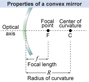
 The first step in ray tracing for a spherical mirror is to draw the optical axis. The optical axis (or principal axis) is the path of a light ray traveling down the center of the optical system. For a spherical mirror, the optical axis is a line perpendicular to the mirror’s surface at its center and passing through the center of curvature. Halfway between the center of curvature and the mirror is the focal point. The focal point is the point through which all incident rays parallel to the optical axis pass (or appear to pass) after they are reflected. The focal point is a very important feature for understanding how a curved mirror reflects light.
|
The focal length of a curved mirror (or a lens!) is the distance between the mirror and its focal point. A simple rule to remember is that the focal length of a spherical mirror is equal to one-half of the radius of curvature. Equivalently, the radius of curvature is twice the focal length. | | | R | = | radius of curvature (m) | | f | = | focal length (m) |
| Radius of curvature
of a spherical mirror |
A mirror with a short focal length (or radius of curvature) has a highly curved surface. A mirror with a very long focal length has a surface that is only slightly curved. As the focal length gets longer and longer the curved surface more closely resembles a flat mirror. 
|
 When tracing rays for a curved mirror, the two most useful rays to trace follow these basic rules. In the next investigation on page 598, these two rules will be used to predict the location and magnification of images formed by curved mirrors.
 - Any incident ray that would pass through the center of curvature is incident normal to the mirror surface and therefore reflects back on itself.
- Any incident ray parallel to the optical axis reflects along a line that passes through the focal point.

 |
The two rules for drawing ray diagrams for curved mirrors are: - Incident light rays on a line through the center of curvature of the mirror reflect back upon themselves; and
- Incident light rays parallel to the optical axis reflect back along a line that passes through the focal point of the mirror.
These rules are very similar to the rules for drawing ray diagrams for curved lenses, as we will see on page 615. 
|

