|
Ray diagrams are a good way to analyze an optical system to find the position, size, and orientation of any images. The procedure is the same for all types of optical systems. To start, several rays are traced leaving at different angles from a single point on an object. If these rays come together again at a point then a real image forms at that point. If the rays leave the optical system and appear to come from some point in space, the point they appear to come from is a virtual image. The following steps describe how to find the image of an arrow in a flat mirror. 
|
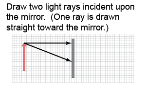 An arrow makes a convenient object for ray tracing. Draw two incident rays from the top of the arrow to the mirror. You can choose any two rays but it is easiest to choose one ray perpendicular to the mirror and the second at an angle.
|
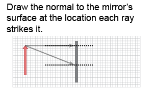 Draw the normals to the surface of the mirror where each incident ray contacts the mirror. The normal is a line perpendicular to the mirror passing through the point of contact. For the top light ray in the figure at right, the normal is along the incident light ray itself—that was the reason for choosing to draw this ray.
|
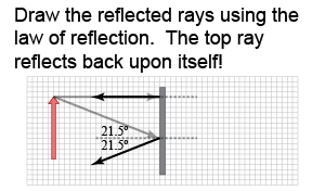 Apply the law of reflection to draw the reflected rays. The top ray makes an angle of 0° with the normal, so the angle of reflection is also 0°. This ray reflects back upon itself. For the bottom ray in the example, the angle of incidence is 21.5° and therefore the angle of reflection is 21.5°.
|
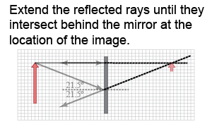 The reflected rays diverge and will not meet in front of the mirror. Nonetheless, those divergent rays appear to come from a point behind the mirror. Extend both reflected rays behind the surface of the mirror. The two extended lines meet at the location of the image of the tip of the arrow.
|
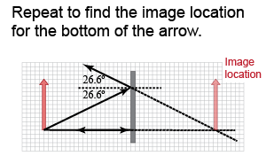 A full image of the arrow includes every point on the arrow. Fortunately, an image’s size and orientation can be found by tracing rays from only two points. Choose the bottom of the arrow as the second point and follow the same steps to find the normals and reflected rays. Extend both reflected rays until they intersect at the image location for the bottom of the arrow.
|
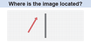 Draw a ray diagram to locate the image of an arrow that is slanted with respect to the mirror.
 |
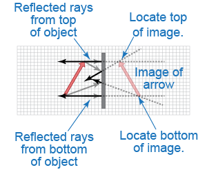 As in the example on this page, draw two incident rays originating from the top of the object arrow, draw their reflected rays, and then extend the reflected rays behind the mirror. The reflected rays intersect at the location of the image of the top of the arrow. Repeat for the bottom of the object arrow.
|

