|
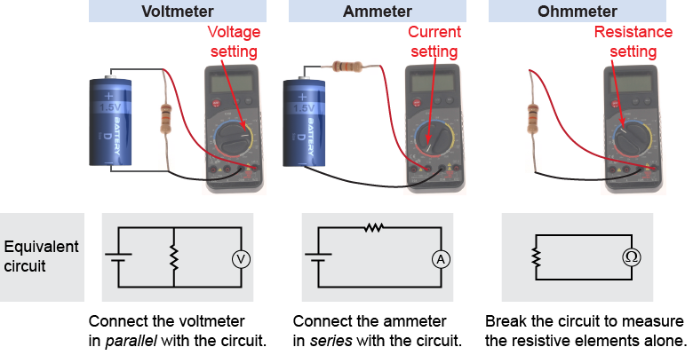
The digital multimeter is a useful instrument that measures voltage, current, and resistance. The digital multimeter in the diagram below has a rotating central knob to select the type of measurement: voltage, current, or resistance. Within each measurement type there may be a number of different range settings. For example, there might be three voltage ranges: 0–2 V, 0–20 V, or 0–200 V. To make the most accurate voltage measurement of a 1.5 V battery you would select the 0–2 V range. 
|

|
Multimeters typically have red and black probe wires, or leads. The probe leads are connected to the matching (+) red and (−) black terminals of the meter. The multimeter must be connected to the circuit in different ways to make different types of measurements. 
|
To measure voltage, the probe leads are touched to two points in a circuit. The meter reads the voltage difference between the two points. If the red lead is at a higher voltage than the black lead, the meter will read a positive value. If the black lead is at the higher voltage, the meter will read a negative value. Note that voltage cannot be measured at one point but only between two points. When the voltage function is selected the multimeter acts as a voltmeter and is represented in a circuit diagram as a circle containing the letter “V.” 
|
To measure current, the meter must be inserted into the circuit, forcing the current to flow through the meter. Current must flow through the multimeter to be measured. When the current function is selected the multimeter acts as an ammeter and is represented in a circuit diagram as a circle containing the letter “A.” 
|
To measure the resistance of a single electrical device the device is isolated from the circuit and connected between the red and black leads of the meter. For most resistance measurements it does not matter which (red or black) lead connects to which terminal of the device being measured. When the resistance (Ω) function is selected the multimeter acts as an ohmmeter and is represented in a circuit diagram as a circle containing the Greek symbol Omega, “Ω.” Most multimeters have resistance ranges from a few ohms to “20 M” (20 MΩ). 
 |
In the illustration above, notice that we have drawn the ohmmeter setting of the multimeter as a circle around a Greek letter Ω for ohms. Surprisingly, there is no standard, accepted symbol for the ohmmeter—this circuit symbol is just what we have adopted for this book! 
|

