|
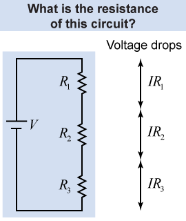
 Consider the circuit in the diagram that has three resistances and a battery connected in series.
- How much current flows in this circuit?
- How is Ohm’s law applied?
The answer is that the current in the circuit adjusts itself so that the sum of all the voltage drops equals the voltage provided by the battery. Since it is a series circuit, the current I is the same everywhere. In mathematics, the battery voltage V equals the sum of the voltage drops across each of the three resistances, R1, R2, and R3: 
|
The current I in the circuit is the same through each resistor; therefore, we can rewrite this equation by grouping the resistances together as Examine this equation and you will see that it looks just like Ohm’s law if we make the identification that the total resistance R of the circuit is equal to the sum of all the individual resistances: This allows us to write the following for the total voltage and the total current: When two or more resistors are connected in series in a circuit, their total combined resistance is given by equation (17.3). The total resistance provides the easiest way to calculate the current in a series circuit. The current in the circuit is the total voltage divided by the total resistance. 
 |
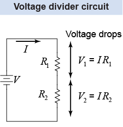
 A frequently encountered circuit is the voltage divider. It is used to change the input voltage in a circuit, such as lowering the voltage when the power supply has a voltage that is too high for the operation of the circuit components.
In its simplest form, the voltage divider is a circuit with two resistors connected in series, such as the one shown here on the right. The total resistance of this circuit is R = R1 + R2. The current I is given by Ohm’s law: The voltage drop V2 across resistor R2 is And the voltage drop V1 across resistor R1 is As an example, consider designing a voltage divider circuit to convert an input voltage of 9 V into an output voltage of 3 V. In order to have a potential difference of 3 V across resistor R2, the ratio of the two resistors is Note that we only know the ratio of the two resistors, not the particular value of each resistor. If we want to set R1 = 10 kΩ, then R2 = 5 kΩ.
More generally, we cannot determine the best values for the two resistors because we do not have enough constraints in our system. In electronics, a typical constraint is a limit on the power dissipated by the circuit because we don’t want the resistors to overheat! We will learn more about power in electric circuits on page 494. 
|
| (17.3) | | | R | = | equivalent resistance (Ω) | | R1 | = | resistance 1 (Ω) | | R2 | = | resistance 2 (Ω) | | R3 | = | resistance 3 (Ω) |
| Equivalent resistance
series resistors |
|
Two resistors with resistances of 10 Ω and 20 Ω are connected in series with a battery of voltage 10 V. What is the current through the circuit? | Asked: | total current I through the circuit | | Given: | voltage V = 10 V; resistances R1 = 10 Ω and R2 = 20 Ω | | Relationships: | Ohm’s law I = V/R;
equivalent resistance for series resistors: Req = R1 + R2 | | Solution: | The equivalent resistance for the series circuit is Req = R1 + R 2 = 10 Ω + 20 Ω = 30 Ω The current is then | | Answer: | I = 0.33 A. | 
|
Seven resistors with resistances of 1, 2, 3, 4, 5, 6, and 7 Ω, respectively, are connected in series. What is their effective resistance?
 |
The resistors are connected in series; therefore, their resistances add directly when calculating the effective resistance: 
|
| |
|

