|
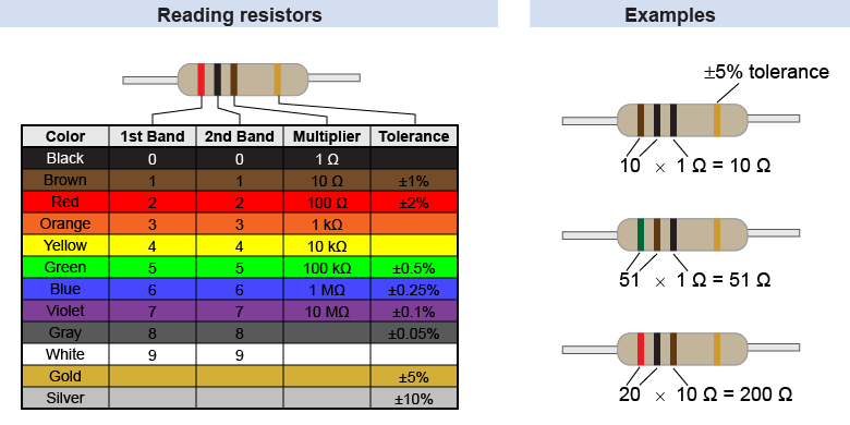
The resistance of a resistor, in ohms, is often coded on its outside using a system of colored bands. Most common resistors have four color bands: three for the value of the resistance and the last band for its tolerance. The tolerance tells you how far off the actual resistance can be compared to the color code value. 
|

|
The first two color bands represent the first two digits of the resistor’s value. In the example above the table, these are red and black, corresponding to 2 and 0, or 20. The third band represents a power of 10 multiplier. The brown third band corresponds to a multiplier of 101 = 10. This resistor therefore has a resistance of 20 × 10 = 200 Ω. The fourth and final band provides the tolerance, which in the example is gold, or 5%. The actual resistance could therefore be anything within ±5%, or 190 Ω to 210 Ω. 
|
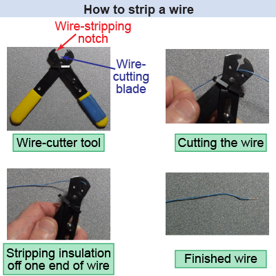
 When constructing circuits, particularly with a circuit breadboard, you will typically need wires that have the insulation removed from both ends. Wires can be purchased with the ends already “stripped,” but you can strip a wire yourself, too. A wire-cutter tool is used for this purpose. It has a sharp blade (like a scissors blade) for cutting off a length of wire. It also has a wire-stripping notch that, when you squeeze it around the wire and pull, will remove the outer insulation while leaving the inner conducting wire in place. Different wire-stripping tools have differently sized notches so that they work on wires with different diameters.
|
| |
|

