| | Essential questions | | How do you build a circuit on a breadboard? | |
|
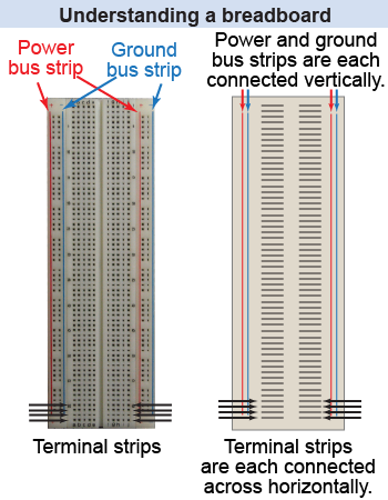
The breadboard is a standard tool for prototyping and designing electronic circuits. A breadboard has holes (or sockets) for inserting wires, lamps, resistors, batteries, and other components. Some holes connect to each other, whereas others do not. This investigation explores how the breadboard works and uses it to build simple circuits. 
 |
How do you strip the insulation off the ends of a wire?
 In this investigation, you will most likely have a collection of wires that already have pieces of their insulation stripped off both ends—so that they can be used with the circuit breadboard. If not, then you will have to use a wire-cutter tool to cut lengths of wire and remove the insulation from both ends, as demonstrated in the illustration at right.
|
Part 1: Exploring the connections on a breadboard

- Use the continuity setting on a device (such as a digital multimeter) to test whether the data acquisition probes are connected to each other.
- Identify three different kinds of connections: power (red), ground (blue), and terminal (black).
- Draw a diagram showing the connections between the holes in the breadboard.
- Where should you connect the positive and negative terminals of a battery?
- Where should you connect other circuit components, such as lamps and resistors?
- How are the holes in a breadboard connected to each other?
 |
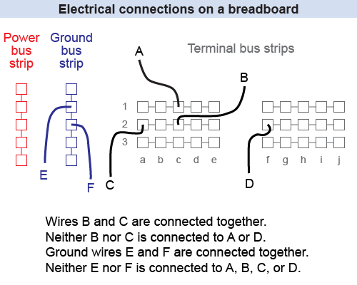
Electrical connections on a breadboard

|
Using the continuity probes on a myDAQ
 The myDAQ is an instrument that delivers various voltages and signals, as well as measures electrical quantities (voltage, current, resistance, or continuity) similarly to a digital multimeter. The instrument can be connected directly to a specialized circuit breadboard so that the voltages are easily accessed. To use it, follow these steps:
 - Plug the myDAQ into your computer using a standard USB cable.
- Insert the green circuit breadboard (such as the Elenco myProtoboard) into the side of the myDAQ.
- Launch the Ergopedia instrument application from your computer.
- In the application, click the “Measurement” tab. A green light will verify that your computer successfully connected to the myDAQ. (The startup connection may take up to 20 s to initialize.)
Within the “Measurement” tab, choose the “Continuity” setting. The figure on the instrument will show you how to connect the red and black probes to the myDAQ for this particular instrument setting. (The connections differ when you want to measure current!)
You should now be ready to follow the directions for Part 1 [above] using the myDAQ.
|
Part 2: Wiring a simple circuit

- Connect power and ground from a +3 V voltage source (or two D-cell batteries) to the breadboard. One lead of this power supply connects to the breadboard’s power strip, while the other connects to the ground strip.
- Insert the socket for one lamp into the breadboard to connect a simple circuit.
- Why do you always wire ground first, with the voltage source off, when connecting a circuit?
- Why are the lamp’s two leads inserted into different terminal strip rows, rather than the same row?
- Does the lamp behave the same or differently when you reverse its connections to power and ground? Explain.
- Modify your circuit to use a piece of wire to act as a switch to turn the lamp on and off. What position of your “switch” makes a closed circuit? What position makes an open circuit? How can you modify your circuit to create a short circuit?
Wiring the simple circuit on a myDAQ
 You can also use the myDAQ instrument to construct this circuit and provide the +5 V voltage source. First follow the instructions above to connect the myDAQ to your computer and launch the Ergopedia instrument application. The protoboard has a label showing you where you can connect wires to the +5 V source; the ground connection is located adjacent to it.
Then you can proceed with wiring the light bulb circuit and answering the questions in Part 2 [above].
| |
| |
|