|
On the previous two pages, you learned the principles behind the operation of the electric motor. What does the inside of a real electric motor inside a power tool or toy look like? How does a real electric motor work? 
|
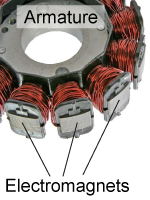
 In the electric motor described up until now, the polarity of the stationary magnet changes to keep the rotor spinning, while the magnets on the rotor have fixed polarity. In many electric motors, however, the rotor magnets are electromagnets and alternate their polarity, while the stationary magnets have fixed polarity. In the image at right, the coil of electric wires, wound around a metallic core, are visible for each of the electromagnets on the rotor. The rotating set of electromagnets in a motor is called the armature.
|
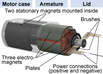
 A typical electric motor found in an electric device is quite small, only 3–10 cm, but it can deliver plenty of power for basic applications. If you take apart an electric motor (and always disconnect it from power before doing so!), you can easily see the working parts inside.
|
In the motor, rotating electromagnets are electrically connected to the power supply through brush contacts that automatically switch the polarity at the right time. There are two brushes, one connected to the positive terminal of the power supply and the other to the negative terminal. At any given time, the brushes make contact with two of three metal plates, each called a commutator, mounted on the axle of the motor. The commutators in turn connect to the electromagnets on the armature. The brushes and commutators work together to switch positive and negative power to the electromagnets. 
|

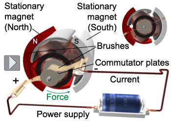
| If you took a snapshot of the electric motor in action, what would the connections inside look like? In the figure at right, the brushes are in contact with two of the commutator plates, causing current to flow from top to bottom of the electromagnet at the top of the armature. Using the right-hand rule, we know that this electromagnet has its south magnetic pole pointing up. The magnetic force between this electromagnet and the two stationary magnets creates a counter-clockwise torque on the armature, causing the armature to rotate. | 
|
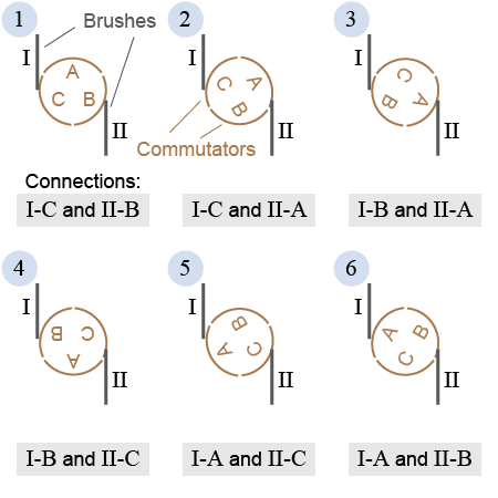
The electric motor illustrated above has three commutator plates and two brushes. These two components connect in six different ways, also called phases, during one rotation of the rotor. Draw a diagram showing all six phases.
 |
 Label the three commutator plates as A, B, and C, and label the two brushes as I and II. The six phases are shown in the figure at right.
|
| |
|

