|
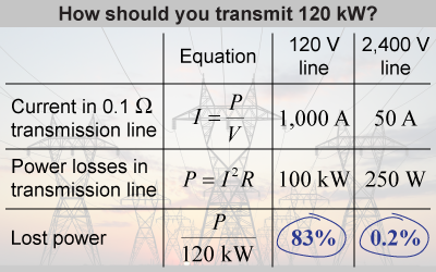
 Power plants are often located far away from the houses they power. What voltage should be used to transmit the electricity? Suppose you wanted to deliver 120 kW of power (enough to supply around 100 houses) through a low-resistance (0.1 Ω) power line. Should you transmit it at 120 V or at 2,400 V? The low-voltage line carries a lot of current, which results in 83% of the power being lost in the transmission lines. This is not good! The high-voltage line performs much better, only losing 0.2% of the power during transmission.
 |
The power losses from resistance in the line increase with current as P = VI = (IR)(I) = I 2R. Since the power losses in the line are proportional to I 2, we should minimize the current in the line. But we want to do this while keeping P = IV constant, because we want to transmit the full 120 kW, regardless. If we make I small, then we have to make V large to keep P constant. This means that we should maximize the voltage in the line! 
|
This is why high-voltage lines are used for long distance transmission of electricity: to reduce power losses in the lines. But how do we change the voltage of the AC transmission line? To do this requires a transformer. 
|

|
A transformer uses mutual induction to transfer electrical power from one transmission line to another. The changing magnetic field produced by the primary coil induces a changing current in the secondary coil. The efficiency of a transformer is increased by winding the coils around a ferromagnetic core, because the magnetic domains in the core align to the magnetic field. A transformer exploits induction by introducing a twist: using a different number of loops in the primary and secondary coils. The induced voltage increases with each additional loop in the secondary coil. But energy (and power) must be conserved! When the induced voltage in the secondary is larger than the primary, the induced current must be smaller. 
|
| (19.3) | | | Vp | = | primary coil voltage (V) | | Vs | = | secondary coil voltage (V) | | Np | = | number of primary coils | | Ns | = | number of secondary coils |
| Transformer voltage
|
|
The ratio of the voltages of a transformer is given by the ratio of the number of coils in the primary and secondary, as shown in equation (19.3). A “step-up” transformer increases the voltage, whereas a “step-down” transformer decreases the voltage. Transformers only work with varying input voltages and currents—such as AC circuits—because only a changing magnetic field will induce a current in the secondary. 
|
Shazi learned in physics class that constant voltages do not induce currents in transformers. She connected a constant +5 V power supply to the primary side of a transformer. To her surprise, when she turned on the power supply, she saw a current briefly induced in the secondary coil, followed by no current. When she turned the power supply off, she also saw a current briefly induced in the secondary coil—but this current flowed in the opposite direction. What's going on?
 |
When Shazi initially connected the circuit, the voltage quickly changed from 0 to +5 V. That change in voltage caused an increasing current to flow through the primary coil, producing an increasing magnetic field. Current was induced in the secondary coil because the flux through that coil was changing, albeit only briefly! Once the voltage reached +5 V and the current and magnetic field of the primary coil reached steady state, the current in the secondary coil vanished. When she turned off the power supply, the voltage and current in the primary coil rapidly decreased, causing a decrease in magnetic flux through the secondary coil. This meant that the induced current in the secondary coil would have the opposite sign—meaning that current briefly flowed in the opposite direction. 
|
In a “step-up” transformer, which coil has more loops, the primary or the secondary?
 |
A step-up transformer increases the voltage, so the output or secondary coil must have more loops than the primary. 
|

