|
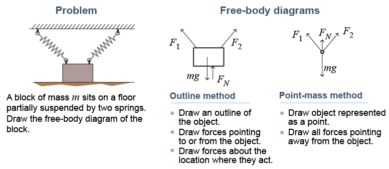
Free-body diagrams are not art, but instead they are a language for describing forces and objects. As with other languages, there are different ways to represent the same information, or “say” the same thing. In this course we have chosen to draw free-body diagrams using the “outline” method. This is the way force diagrams appear in engineering applications, in practical building codes, and also in more advanced physics problems, such as those involving rotation. The other common method is the “point-mass” method, which is used in more theoretical books. 
|
|
Consider a block resting on the floor partially suspended by two springs.
|
 Both free-body diagrams are correct as long as they correctly identify only the forces acting on the object and correctly label every force.
|
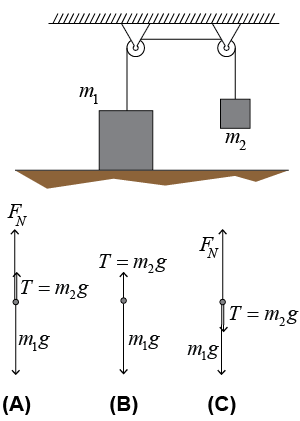
The diagram (below right) shows two masses connected by a rope that passes over two frictionless pulleys. Which of the three point-mass-style free-body diagrams best represents the forces acting on mass m1? Explain why the other two are incorrect. 
|

| Asked: | Choose the best free-body diagram for the forces acting on mass m1. | | Given: | three free-body diagrams | | Solution: | There are three forces: weight m1g, a normal force from the floor FN, and the rope tension T, which equals the weight m2g of mass m2.
Only diagram (A) shows all three forces in the correct directions.
Diagram (B) omits the normal force from the floor.
Diagram (C) shows the tension T acting down on mass m1, which is incorrect because this force acts through the rope and should be pulling up on m1. |
|
| |
|

