|
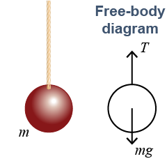
 A free-body diagram is a geometric sketch of an object isolated from everything else except for the forces that act on it. A key idea in a free-body diagram is that every interaction the object has with the environment is replaced by the force that interaction makes on the object. That means every supporting surface, rope, spring, weight, and even friction appear on the diagram only as forces, not as sketches of the actual objects. In the example, the rope is replaced by the tension force T exerted by the rope on the ball.
 |
Each force on a free-body diagram is represented by an arrow. The arrow points either toward the object or away from the object depending on the direction of the force and the style of the diagram. Each force arrow should be located as close as possible to the actual point where the force acts. This is often the same point where objects touch each other. For example, the force from the rope is drawn from the point where the rope attaches. 
|
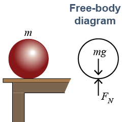
 The “all” in “all the forces” means that, if you remove the object completely from its environment, the object behaves the same. If a ball is resting on a table, then the free-body diagram replaces the table with a force that allows the ball to remain at rest. The force from the table is called a normal force. Normal forces, also called support forces, are created at every point where two objects touch each other, such as between the ball and the table. In the example, the normal force is FN.
|
Normal forces point perpendicular to the surface of contact between objects and always provide a push. If the surfaces are curved, then the normal force is along the line of contact between the surfaces. The diagram below shows some examples. 
|

|
A free-body diagram needs to be neither exact nor artistic! A good free-body diagram is just an outline of the object that shows the approximate locations and assumed directions and names of the forces acting on each single object. The above-right diagram contains two balls, and each one gets its own free-body diagram. Equally important is that each unique force must have a unique name. In the example we use subscripts to name the four different forces F1, F2, F3, and F4. 
 |
If you look carefully you see that force F3 appears twice. This force acts downward on ball #1 and upward on ball #2. In the next section we explain that forces always occur in action–reaction pairs that are equal in strength and opposite in direction. The two forces F3 are an action–reaction pair. These forces have the same numerical strength—hence the same variable name. They also have different directions and act on different objects. 
|
A tricky aspect of drawing free-body diagrams is to identify all the forces that act and to include only those forces that act on the object. The phrase “on the object” is important because there may be forces that come from the object but act on something else. 
|
Which forces are drawn on a free-body diagram of an object? - only those forces that are exerted by the object
- only those forces that are exerted on the object
- all forces exerted on or by the object
 |
The answer is b. Only those forces that act on the object should appear on its free-body diagram. The forces that act on an object determine its motion. 
|

