|
The most common use of parallel plate capacitors is in small devices in electric circuits or electronics boards. In these electrical applications, the stored charge on the capacitor can be calculated using equation (18.7), and the stored electrical potential energy can be calculated using equation (18.8). 
|
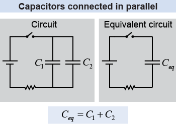
 When more than one resistor is connected, the properties of the circuit can be modeled using an equivalent resistance, as you learned on page 488. Similarly, two or more capacitors in a circuit can be modeled with an equivalent capacitance. When connected in parallel, the total charge on each capacitor is q = CV, so the combined charge is This means that the equivalent capacitance is the direct sum of the individual capacitances (C1 + C2) when they are connected in parallel.
|
| (18.10) | | | Ceq | = | equivalent capacitance (F) | | C1 | = | capacitance #1 (F) | | C2 | = | capacitance #2 (F) |
| Equivalent capacitance
connected in parallel |
|
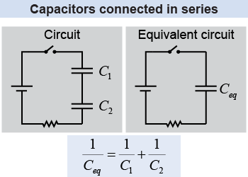
 When two capacitors are connected in series, the charge collected on each capacitor must be the same because of conservation of charge. In other words, the negative charges that build up on the plate of C1 must be equal but opposite to the charges that build up on the positive plate of C2 because the electrical wire between the capacitors is isolated and electrically neutral. The total voltage across the two capacitors is the sum of the voltages across each capacitor, or V = V1 + V2. The individual capacitors have charges q = C1V1 and q = C2V2. The ratio of charge to effective capacitance is equal to this combined voltage:
|
| (18.11) | | | Ceq | = | equivalent capacitance (F) | | C1 | = | capacitance #1 (F) | | C2 | = | capacitance #2 (F) |
| Equivalent capacitance
connected in series |
|
Resistances add directly when connected in series, but they add as reciprocals (inverses) when connected in parallel. It is the opposite for capacitors! Capacitances add directly when connected in parallel, but they add as reciprocals when connected in series. 
|

